Friday, September 30, 2016

A minimalist problem solving model that avoids the creep in of the law of instrument (Maslow's hammer)

This blog article presents a simple model to help avoid the creep in of subtle (or not!) effects of the law of instrument (Maslow's hammer) while problem solving in general. This is applicable to research projects with partners across organisational, geographic boundaries in particular.

A minimalist model for problem solving for business and research projects

At the outset, the model differentiates between and isolates the domains of the problem and the solution. It is important to understand stakeholders' needs 'independent of' and 'in isolation from' technology, known and previously produced solutions thereby focusing purely on the problem. Chances are better that this approach could lead to new innovative 'thought out of the box solutions'.

At the very least, it avoids the expertise in the solution domain introducing the effect of the law of instrument (Maslow's Hammer). That is 'I have a hammer (solution) and everything (problem) looks like a nail to me'.

The model (shown in the diagram above) is derived from the text description in the article from the year 2000 - Features, Use Cases, Requirements, Oh My! - by Dean Leffingwell. The diagram elaborates only high level objects and their relationships and links the problem and solution domains. After this level, it is possible to extend the model by introducing objects that are unique to one's needs (for e.g. use cases, pre-conditions, post-conditions etc.).

This is a minimalist model and in particular it has been effectively used by EU research projects such as STREETLIFE (an FP7 funded research project) for all project members to quickly align with the purpose and goal (the big picture) of their activities. The model is introduced in the deliverable D2.2.2 Blueprint Architecture, Security Architecture and Pilot Specific Architectures (Intermediate) and is effectively employed for the mobility management and control panel (MMECP) use case descriptions.


References

  1. Features, Use Cases, Requirements, Oh My! - Dean Leffingwell, SVP, Rational Software, 2000
  2. The law of Instrument, Maslow's Hammer
  3. STREETLIFE Deliverable D2.2.2
    1. Blueprint Architecture, Security Architecture and Pilot Specific Architectures (Intermediate)
    2. Download the document from the Cordis Europa Site here
  4. The STREETLIFE project on the Cordis Europa Site
  5. The STREETLIFE project website

Saturday, March 12, 2016

A framework for an Integrated Technical Architecture in EU research projects with a geographically and organisationally distributed partner setup

Disclaimer: The author of this blog entry is also the editor/co-author of the document which describes the Technical Architecture Integration Concept that this blog entry recommends/promotes as a best practice for EU commission funded research projects.
Getting straight to the point, this deliverable document from the STREETLIFE project (available here @ CORDIS which is the European Commission's primary public repository and portal to disseminate information on all EU-funded research projects and their results) has to offer "a reusable framework for an early approach within European Union (EU) research projects with a distributed partner/pilot platform setup to arrive at an integrated technical architecture". Although, this could generally also be applied in situations where a Software Architect needs to work with a cross organisational distributed setup for research or business projects. To understand the background and associate it with the need for an integrated technical architecture in your architecture projects, continue reading further.

1. For WHOM is this relevant?

In general, the approaches try to address working with constraints put forth by organisational and geographical boundaries when working within projects that are setup with teams picked across organisations and regions. In my opinion, this is a pattern that occurs often within many EU projects commissioned by the former FP7 or the newer Horizon 2020 framework. Hence, this article is particularly relevant for Software Architects working in such projects.

2. WHY?

Mel Conway from his 1967 paper on "How committees invent?" submitted to the Harvard Business Review states
"Any organization that designs a system (defined broadly) will produce a design whose structure is a copy of the organization's communication structure."
Therefore, the structure of the software built by partners within an EU project will tend to reflect the social boundaries of the organization(s) that produced it. EU projects are in general composed of partners that are distributed across the European Union and have completely disconnected managements, software development processes, test and deployment environments. As a result, the architectures of software built within an EU project is bound to be under duress. This is due to the organisational architecture of the partners within the project which defines the communication structure from which the definition of the architecture design is derived.

In my opinion, at the beginnings of many EU projects with a distributed team/pilot/partner setup, it is highly unlikely that all architectural views and viewpoints are laid out and most importantly 'agreed' upon by all partners. It might be that the Architect will need to define such architectural views during the early part of the project's lifetime for addressing the purpose/goals of the project. Development work can only begin after some high level views and viewpoints are agreed upon.

A collaborative pattern persists in EU projects of this nature. There are partners from many EU corporate companies, EU city administrations, EU research institutes/universities that participate in the project jointly.

Probability is high that the partners will have their own development and deployment environments to satisfy their own local experiments. Therefore, having a common software platform in most instances is not a viable option.

This normally leads to conflicting requirements within the project. An example below,
  • Requirements from the EU commission's project office that the partners'/cities' platforms should work in a completely connected way as a necessity to provide concrete re-usable results, standalone software components at the end of the project. 
This conflicts with the following,
  • Requirements from partners within the project that their platforms need to work independently due to intellectual property restrictions, data privacy restrictions or speed of deployment or control restrictions.
These constraints complicate the overall system architecture. More such constraints are described in the D2.2.2 deliverable document within the context of the STREETLIFE project.

3. HOW? 

In particular, within the scope of the projects it should be avoided right from the start that similar solution components are developed in each city's pilot site leading to a 'reinventing the wheel' phenomenon. Ideally, the solution components needed across all pilots are shared after it is agreed upon where it is to be built within the project. Ideally, the pilots also develop common project goals and evolve them into scenarios that involve some process orchestrations across different city pilot solution components.

The document in focus here (Deliverable D2.2.2 from the STREETLIFE project) attempts to address all these constraints and generalize all the solutions into a framework that could be reused/reapplied within EU research projects with a distributed team/partner/pilot setup similar to STREETLIFE. For details, one can always lookup the document from the link above or from the references section. These concepts are based on the Integration Architecture concept from the 'Managed Evolution' book by Stephan Murer and Bruno Bonati.

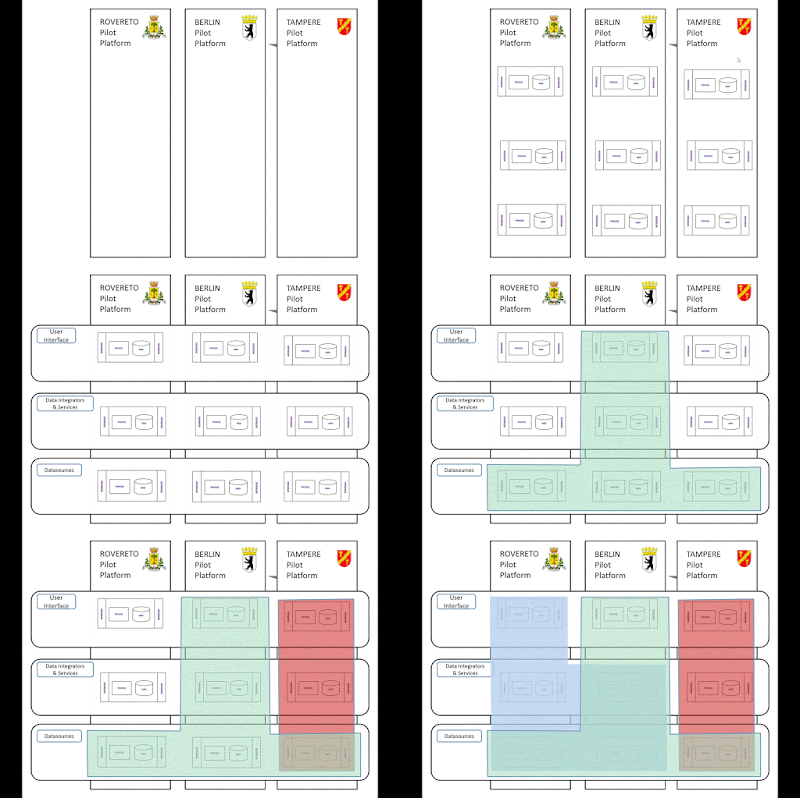
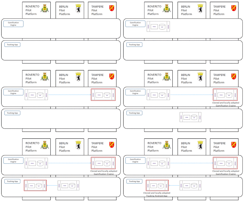
In summary, the deliverable details how to define integration in your projects and then defines two concepts - vertical and horizontal (gif animations below) through with many constraints presented can be handled.

Vertical or Scenario based Integration Concept

Horizontal or Component based Integration Concept

4. REFERENCES


  1. STREETLIFE Deliverable D2.2.2
    • Blueprint Architecture, Security Architecture and Pilot Specific Architectures (Intermediate)
    • Download the document from the Cordis Europa Site here
  2. The STREETLIFE project on the Cordis Europa Site
  3. The STREETLIFE project website
  4. CORDIS - the European Commission's primary public repository and portal to disseminate information on all EU-funded research projects and their results in the broadest sense
  5. Managed Evolution - Stephan Murer and Bruno Bonati

Thursday, February 11, 2016

Software Architecture Communication Tweaks

This article describes a software architecture communication tweak that could potentially be applied with low effort in development projects with 20-30 developers. Although, in my opinion, with some tooling support this is scalable and can be applied to larger development projects too.

1. Why?

As a Software Architect, do you feel the need to
  • use UML based sketches to express designs within your team?
  • have your design documentation and code housed in one project artifact?
  • enable easy acceptance of documentation needs within development teams?
  • delegate the creation/maintenance of designs to developers? 
  • aggregate individual designs into a 'big picture overview' of the architecture? 
  • have the latest versions of designs accessible at all times to all stakeholders?
  • be able to view these designs without additional software (preferably in a browser)?

2. How?

2.1 Get a buy-in from the development team

The objective is to get development teams to agree to create and maintain designs of structure and behavior of components in their area of responsibility.

This might be easier if the Architect's documentation methodology does not take the development team away from their favorite and familiar development environments. It should also not introduce new tools and additional work for the development team.

Most often than not, from a developer's perspective, it helps if the designs can be expressed in a 'code like' fashion within familiar development environments.

It also helps if the code and its design are co-located. That way, the developer who makes code changes can also make changes to the design that the code expresses. And with a little bit of discipline and perseverance ... viola! they are both in sync. Anytime you as a Software Architect look it up you are viewing the latest state of the design and code.

2.2 Marry code and design

Employ PlantUML. It is a simple way to 'code' UML that can be rendered into images by GraphViz. PlantUML is used to draw UML diagrams, using simple and human readable text descriptions. Due to its code like form PlantUML can be easily embedded directly within your code so that there are no 'two' separate locations where the design and the code live for their happily ever afters.

2.3 Version designs

Hopefully, you already version your code! Since the code and design 'live' together it is natural to use the same system to version your designs as well. A version system (for e.g. SVN or Git based Server) that is setup in your local network and also has web interfaces is ideal for the next steps.

2.4 Make the versioned designs accessible

2.4.1 Viewing designs via a consolidated architecture documentation

If you already have a documentation model for your architecture, you will need to figure out how to embed and render the PlantUML images in their latest avatars in your documentation. For example, if your architecture documentation was within a wiki, it should be easy to embed the images that PlantUML rendering software can output image files accessible via URLs on your version system. You could even think of embedding these images within the markdown files within your version system's wiki itself.

2.4.2 Viewing individual designs directly within a browser

To enable your browser to directly render PlantUML code you might want to install the PlantUML Viewer - a PlantUML rendering Chrome Plugin.

3. Sample Implementations with GitHub

Here are a few samples that use GitHub as the version system and also as an interface where consumers of the architecture can access the latest version.

Requirements to view the diagram directly in a browser

NOTE: This does not work on your mobile's google chrome browser since the chrome plugin is not available for it.

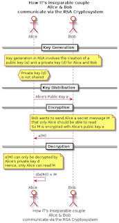
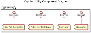
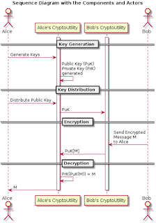
Once you have the above installed you are all set! Just navigate to the links in the list below and you should see the PlantUML text rendered into UML diagrams directly in your browser. Rendered images are also attached below this list for your reference - these images are what you should see when you click on the links below.
  1. A simplified RSA CryptoSystem based communication expressed as a sequence diagram
    1. Structural design expressed using a Component Diagram  
    2. Behavioral design expressed using a Sequence Diagram
    You can download the source code for these PlantUML text files on GitHub.

    A Simplified RSA CryptoSystem based communication
    A Simplified RSA CryptoSystem based communication

    Structural Design of the CryptoUtility Package
    Structural Design of the CryptoUtility Package

    Behavioral Design of the Actors interacting with the CryptoUtility Package
    Behavioral Design of the Actors interacting with the CryptoUtility Package

    4. Conclusion

    In summary, an architecture needs to be descriptively documented, communicated and accessible in its current version to all stakeholders as it evolves over time. As an architecture evolves, chances are that its current version as implemented and the documentations are not in sync. Keeping them in sync and enabling easy access to the latest version of the architecture to all stakeholders are challenges.

    The methods described in this article are ways that a Software Architect can ensure that stakeholders with the responsibility to create and update architectural designs can do so easily and effectively and stakeholders who read the architecture are always provided with the latest version of the architecture. Thereby closing the gap between production and consumption of architectural designs and effectively enhancing architecture communication within the development and management organisations.

    5. References

    1. Plant UML - PlantUML is used to draw UML diagrams, using simple and human readable text descriptions. 
    2. PlantUML Viewer - A chrome plugin by Peter Prikryl
      1. If you like this plugin, support the original author via the PayPal button on the PlantUML site
    3. The GitHub Project - Get all examples shown in this article
    4. PlantText - The PlantText tool is an online tool for quickly creating UML diagrams
    5. Alice and Bob: IT's inseparable couple