This article describes a software architecture communication tweak that could potentially be applied with low effort in development projects with 20-30 developers. Although, in my opinion, with some tooling support this is scalable and can be applied to larger development projects too.
1. Why?
As a Software Architect, do you feel the need to- use UML based sketches to express designs within your team?
- have your design documentation and code housed in one project artifact?
- enable easy acceptance of documentation needs within development teams?
- delegate the creation/maintenance of designs to developers?
- aggregate individual designs into a 'big picture overview' of the architecture?
- have the latest versions of designs accessible at all times to all stakeholders?
- be able to view these designs without additional software (preferably in a browser)?
2. How?
2.1 Get a buy-in from the development team
The objective is to get development teams to agree to create and maintain designs of structure and behavior of components in their area of responsibility.
This might be easier if the Architect's documentation methodology does not take the development team away from their favorite and familiar development environments. It should also not introduce new tools and additional work for the development team.
It also helps if the code and its design are co-located. That way, the developer who makes code changes can also make changes to the design that the code expresses. And with a little bit of discipline and perseverance ... viola! they are both in sync. Anytime you as a Software Architect look it up you are viewing the latest state of the design and code.
2.2 Marry code and design
Employ PlantUML. It is a simple way to 'code' UML that can be rendered into images by GraphViz. PlantUML is used to draw UML diagrams, using simple and human readable text descriptions. Due to its code like form PlantUML can be easily embedded directly within your code so that there are no 'two' separate locations where the design and the code live for their happily ever afters.2.3 Version designs
Hopefully, you already version your code! Since the code and design 'live' together it is natural to use the same system to version your designs as well. A version system (for e.g. SVN or Git based Server) that is setup in your local network and also has web interfaces is ideal for the next steps.2.4 Make the versioned designs accessible
2.4.1 Viewing designs via a consolidated architecture documentation
If you already have a documentation model for your architecture, you will need to figure out how to embed and render the PlantUML images in their latest avatars in your documentation. For example, if your architecture documentation was within a wiki, it should be easy to embed the images that PlantUML rendering software can output image files accessible via URLs on your version system. You could even think of embedding these images within the markdown files within your version system's wiki itself.2.4.2 Viewing individual designs directly within a browser
To enable your browser to directly render PlantUML code you might want to install the PlantUML Viewer - a PlantUML rendering Chrome Plugin.
3. Sample Implementations with GitHub
Here are a few samples that use GitHub as the version system and also as an interface where consumers of the architecture can access the latest version.Requirements to view the diagram directly in a browser
- A recent version of the Google Chrome Browser on your desktop PC.
- PlantUML Viewer - a PlantUML rendering Chrome Plugin
NOTE: This does not work on your mobile's google chrome browser since the chrome plugin is not available for it.
Once you have the above installed you are all set! Just navigate to the links in the list below and you should see the PlantUML text rendered into UML diagrams directly in your browser. Rendered images are also attached below this list for your reference - these images are what you should see when you click on the links below.
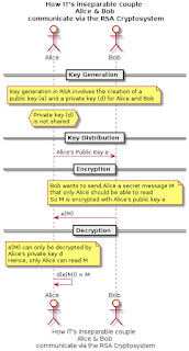
- A simplified RSA CryptoSystem based communication expressed as a sequence diagram
- A sequence of actions and communications between IT's inseparable couple Alice & Bob
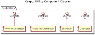
- Structural design expressed using a Component Diagram
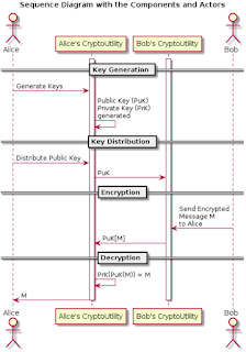
- Behavioral design expressed using a Sequence Diagram
You can download the source code for these PlantUML text files on GitHub.
 |
| A Simplified RSA CryptoSystem based communication |
 |
| Structural Design of the CryptoUtility Package |
 |
| Behavioral Design of the Actors interacting with the CryptoUtility Package |
4. Conclusion
In summary, an architecture needs to be descriptively documented, communicated and accessible in its current version to all stakeholders as it evolves over time. As an architecture evolves, chances are that its current version as implemented and the documentations are not in sync. Keeping them in sync and enabling easy access to the latest version of the architecture to all stakeholders are challenges.The methods described in this article are ways that a Software Architect can ensure that stakeholders with the responsibility to create and update architectural designs can do so easily and effectively and stakeholders who read the architecture are always provided with the latest version of the architecture. Thereby closing the gap between production and consumption of architectural designs and effectively enhancing architecture communication within the development and management organisations.
5. References
- Plant UML - PlantUML is used to draw UML diagrams, using simple and human readable text descriptions.
- PlantUML Viewer - A chrome plugin by Peter Prikryl
- If you like this plugin, support the original author via the PayPal button on the PlantUML site
- The GitHub Project - Get all examples shown in this article
- PlantText - The PlantText tool is an online tool for quickly creating UML diagrams
- Alice and Bob: IT's inseparable couple
Nice article Yogesh!
ReplyDeleteMakes sense and well written!
ReplyDeleteMakes sense and well written!
ReplyDeleteI used plantuml recently and I love it. It gets a bit tricky to get a proper layout with large and complex diagrams, so it might make sense to split them (high level first, detailed section next).
ReplyDeleteAdditionally, I would recommend using markdown notes files (.md) for anything that cannot go into a diagram (e.g. installation procedures, project background info). This way, developers can maintain all documentations together with the code in one place. This allows the Architect to get a quick overview of progress and changes.
Yes, I agree. Markdown is the way to go for documenting text.
ReplyDeleteAlso many versioning systems come with wikis as part of their ecosystem. Gitlab for example uses Gollum I think. So each developer can have a local wiki, write notes in the wild with no internet and merge changes to the central wiki when connected.